Week of 05/28/22 - 06/03/22
- Jun 4, 2022
- 5 min read
Updated: Jul 5, 2022
Group:
This week the group focused on the atmospheric conditions working together simultaneously in order to detect the different conditions listed on the flowchart. Construction of the speed limit sign was started along with wiring the sensor together.
Below is the set up so far of the speed limit sign. The solar panel is placed on the top in order to gain as much access from the sun as possible. The solar panel is placed far enough above the speed limit sign to ensure no obstruction views for the drivers.
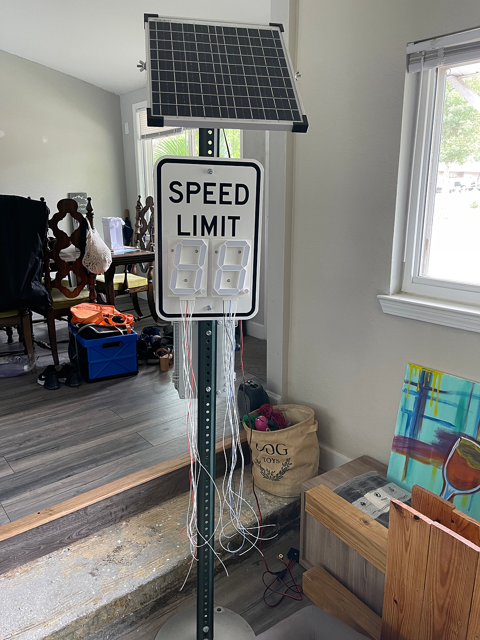
The 7-segment displays are placed on the speed limit sign beside one another to replicate an actual speed limit sign. The wires shown below will be rerouted to the housing located behind the sign where it will be connected to the micro controller.
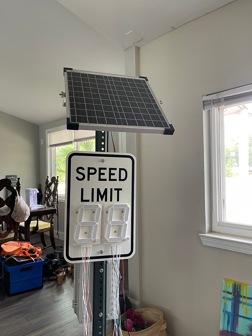
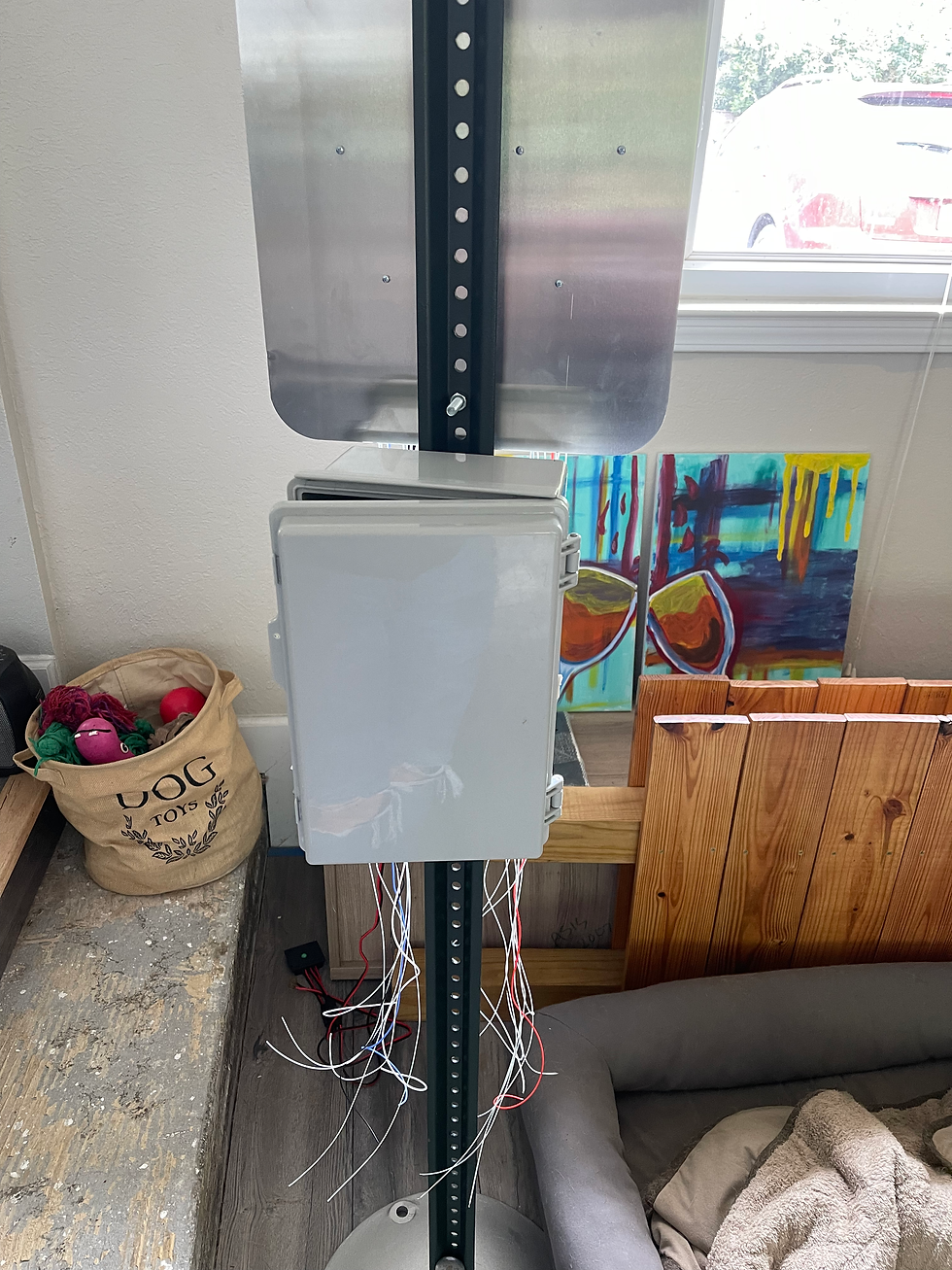
This waterproof housing below will be the hub for the micro controller along with GSM module. The housing will act as the protection to the devices against all possible weather conditions that the sign may endure.
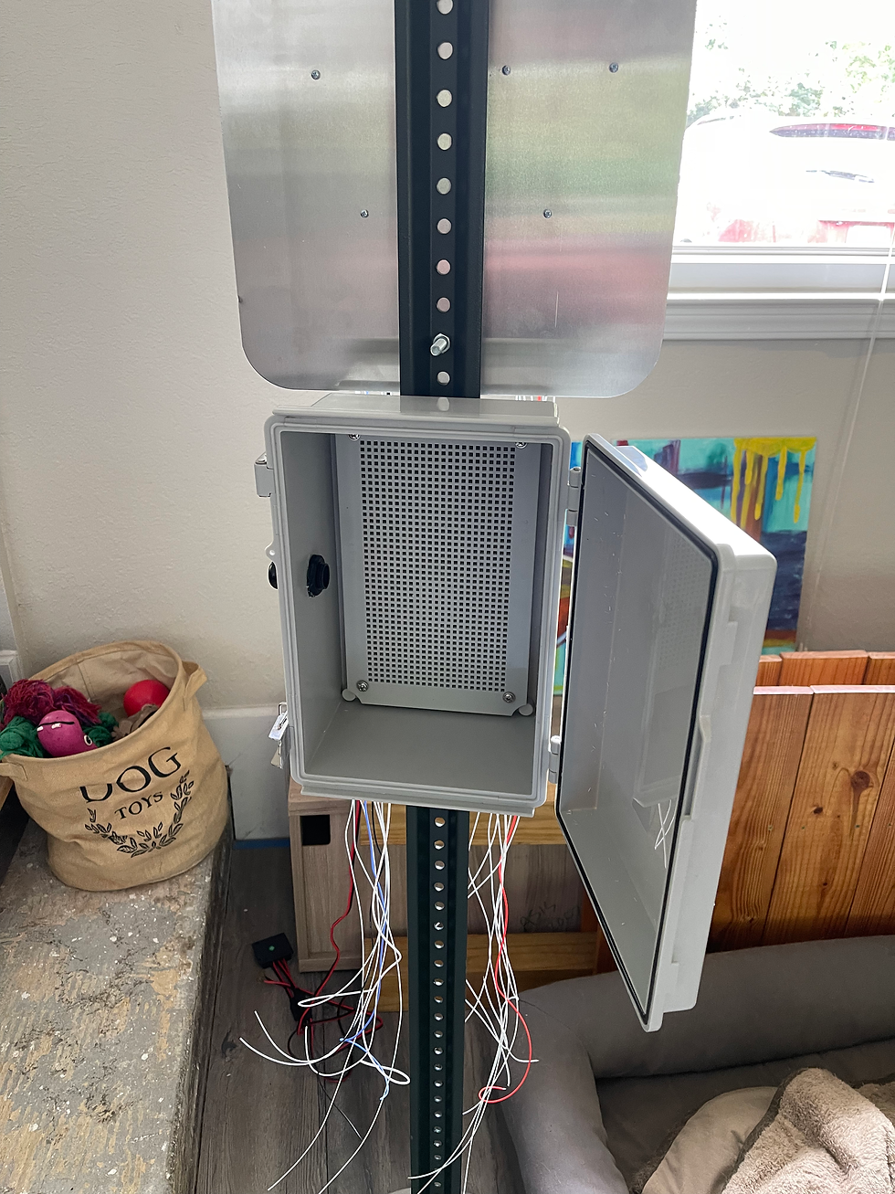
This is an open view of the waterproof hosing where the microcontrollers will be placed.
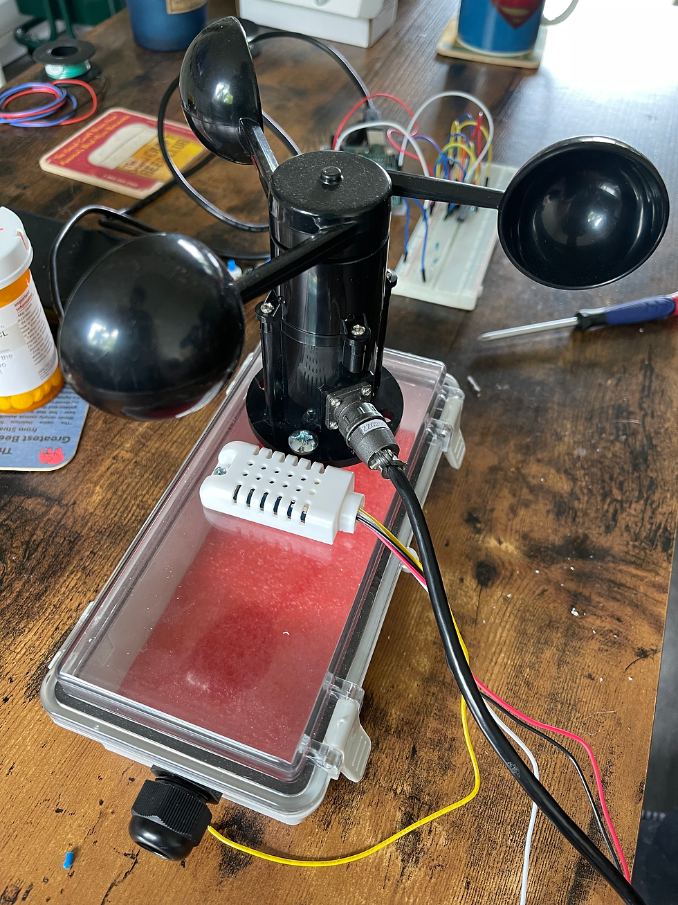
The housing below will be the hub for all the sensors. As shown in the picture, the housing has a clear top. The clear top gives us the ability to keep some of the sensors that may be more delicate inside the housing to ensure safety from the possible weather conditions while still allowing the sensor to complete its job. For example: The light sensor will be one of the delicate sensors that will remain inside the housing. The sensor will still be able to light but will not have to withstand different weather conditions.
Below the wind sensor and temperature sensor are connected to the top of the housing. The rain sensor will also be attached to the top of the housing beside the temperature sensor. The placement of the sensors is to ensure maximum exposure to the weather conditions in order to gain the correct current condition.
The atmospheric code was a big focus this week to give the sensors the ability to work together to be able to determine the different cases needed in order to change the speed limit.
Jeremy:
//-------------------
// Beginning of Code for Atmospheric Arduino
//-------------------
#include <Wire.h>
#define Addr 0x44
const int wind = A0; // Wind Sensor connected to the pin A0
const int light = A1; // Photosensor connected to the pin A1
const int rain = A2; // Rain Sensor connected to the pin A2
const int temp = A3; // Temperature Sensor connected to the pin A3
const int masterL = 4; // Master Arduino LSB connected to digital pin 4
const int masterM = 7; // Master Arduino MSB connected to digital pin 7
int masterVal = 0; // Variable to store the value
void setup() {
// sets the function of the pin
pinMode (wind, INPUT); // sets the pin A0 as input
pinMode (light, INPUT); // sets the pin A1 as input
pinMode (rain, INPUT); // sets the pin A2 as input
pinMode (temp, INPUT); // sets the pin A3 as input
pinMode (masterL, OUTPUT); // sets the pin 7 as output
pinMode (masterM, OUTPUT); // sets the pin 8 as output
Wire.begin();
Serial.begin(9600);
delay(10000);
}
void loop() {
// Establish 6 bytes of data to be stored
unsigned int data[6];
// Start I2C Transmission
Wire.beginTransmission(Addr);
// Send measurement command
Wire.write(0x2C);
Wire.write(0x06);
// Stop I2C transmission
Wire.endTransmission();
delay(500);
// Request 6 bytes of data
Wire.requestFrom(Addr, 6);
// Read 6 bytes of data
// Temp msb, Temp lsb, Temp crc, humidity msb, humidity lsb, humidity crc
if (Wire.available() == 6){
data[0] = Wire.read();
data[1] = Wire.read();
data[2] = Wire.read();
data[3] = Wire.read();
data[4] = Wire.read();
data[5] = Wire.read();
}
// Initalized the analog inputs
int windVal = analogRead (wind);
int lightVal = analogRead (light);
int rainVal = analogRead (rain);
float tempVal = ((((((data[0] * 256.0) + data[1]) * 175) / 65535.0) - 45) * 1.8) + 32;
float windVolt;
float lightVolt;
digitalWrite(masterL, LOW);
digitalWrite(masterM, LOW);
// Convert analog inputs to read voltages
windVolt = windVal * 0.004882814; // Converting input value to voltage
lightVolt = lightVal * 5.0 / 1023; // Converting input value to voltage
// The "if" condition of Setting masterVal to 2 (To Raise Speed Limit)
if (windVolt < 0.52 && lightVolt > 0.2 && rainVal > 500 && tempVal > 55) {
// masterVal is set to 2
masterVal = 2;
digitalWrite(masterL, LOW);
digitalWrite(masterM, HIGH);
Serial.print("The Wind Voltage is "); Serial.print(windVolt); Serial.print("\n");
Serial.print("The Light Voltage is "); Serial.print(lightVolt); Serial.print("\n");
Serial.print("The Rain Voltage is "); Serial.print(rainVal); Serial.print("\n");
Serial.print("The Temp Value is "); Serial.print(tempVal); Serial.print("\n");
Serial.print("Based of Atmosphereic Condition: Raise the Speed Limit"); Serial.print("\n");
Serial.print(masterL); Serial.print(masterM); Serial.print("\n\n");
}
// The "else if" condition statement will set masterVal to 1 (To Lower Speed Limit)
else if (rainVal <= 500 || windVolt > .52 && tempVal < 55 && rainVal > 500) {
// masterVal is set to 1
masterVal = 1;
digitalWrite(masterL, HIGH);
digitalWrite(masterM, LOW);
Serial.print("The Wind Voltage is "); Serial.print(windVolt); Serial.print("\n");
Serial.print("The Light Voltage is "); Serial.print(lightVolt); Serial.print("\n");
Serial.print("The Rain Voltage is "); Serial.print(rainVal); Serial.print("\n");
Serial.print("The Temp Value is "); Serial.print(tempVal); Serial.print("\n");
Serial.print("Based of Atmosphereic Condition: Lower the Speed Limit"); Serial.print("\n");
Serial.print(masterL); Serial.print(masterM); Serial.print("\n\n");
}
// The "else" condition statement will set masterVal to 0 (Remain at Default Speed)
else {
// masterVal is set to 0
masterVal = 0;
digitalWrite(masterL, LOW);
digitalWrite(masterM, LOW);
Serial.print("The Wind Voltage is "); Serial.print(windVolt); Serial.print("\n");
Serial.print("The Light Voltage is "); Serial.print(lightVolt); Serial.print("\n");
Serial.print("The Rain Voltage is "); Serial.print(rainVal); Serial.print("\n");
Serial.print("The Temp Value is "); Serial.print(tempVal); Serial.print("\n");
Serial.print("Based of Atmosphereic Condition: No Change to the Speed Limit"); Serial.print("\n");
Serial.print(masterL); Serial.print(masterM); Serial.print("\n\n");
}
}
Destany:
This week I focused on the creating the code for the display numbers.
// 7 Segment Display
int segPins[] = {9, 8, 7, 6, 5, 4, 3, 2 };
int displayPins[] = {10, 11};
int displayBuf[2];
byte segCode[10][8] = {
// 7 segment code table
// a b c d e f g .
{ 1, 1, 1, 1, 1, 1, 0, 0}, // 0
{ 0, 1, 1, 0, 0, 0, 0, 0}, // 1
{ 1, 1, 0, 1, 1, 0, 1, 0}, // 2
{ 1, 1, 1, 1, 0, 0, 1, 0}, // 3
{ 0, 1, 1, 0, 0, 1, 1, 0}, // 4
{ 1, 0, 1, 1, 0, 1, 1, 0}, // 5
{ 1, 0, 1, 1, 1, 1, 1, 0}, // 6
{ 1, 1, 1, 0, 0, 0, 0, 0}, // 7
{ 1, 1, 1, 1, 1, 1, 1, 0}, // 8
{ 1, 1, 1, 1, 0, 1, 1, 0} // 9
};
void refreshDisplay(int digit1, int digit0)
{
digitalWrite(displayPins[0], HIGH); // displays digit 0 (least significant)
digitalWrite(displayPins[1],LOW );
setSegments(digit0);
delay(5);
digitalWrite(displayPins[0],LOW); // then displays digit 1
digitalWrite(displayPins[1], HIGH);
setSegments(digit1);
delay(5);
}
void setSegments(int n)
{
for (int i=0; i < 8; i++)
{
digitalWrite(segPins[i], segCode[n][i]);
}
}
void setup()
{
for (int i=0; i < 8; i++)
{
pinMode(segPins[i], OUTPUT);
}
pinMode(displayPins[0], OUTPUT);
pinMode(displayPins[1], OUTPUT);
displayBuf[1] = 0; // initializes the display
displayBuf[0] = 0;
}
int i = 0, j = 0;
int startTime = 0;
int endTime;


Comments